LUXBOARD A
Der Standard
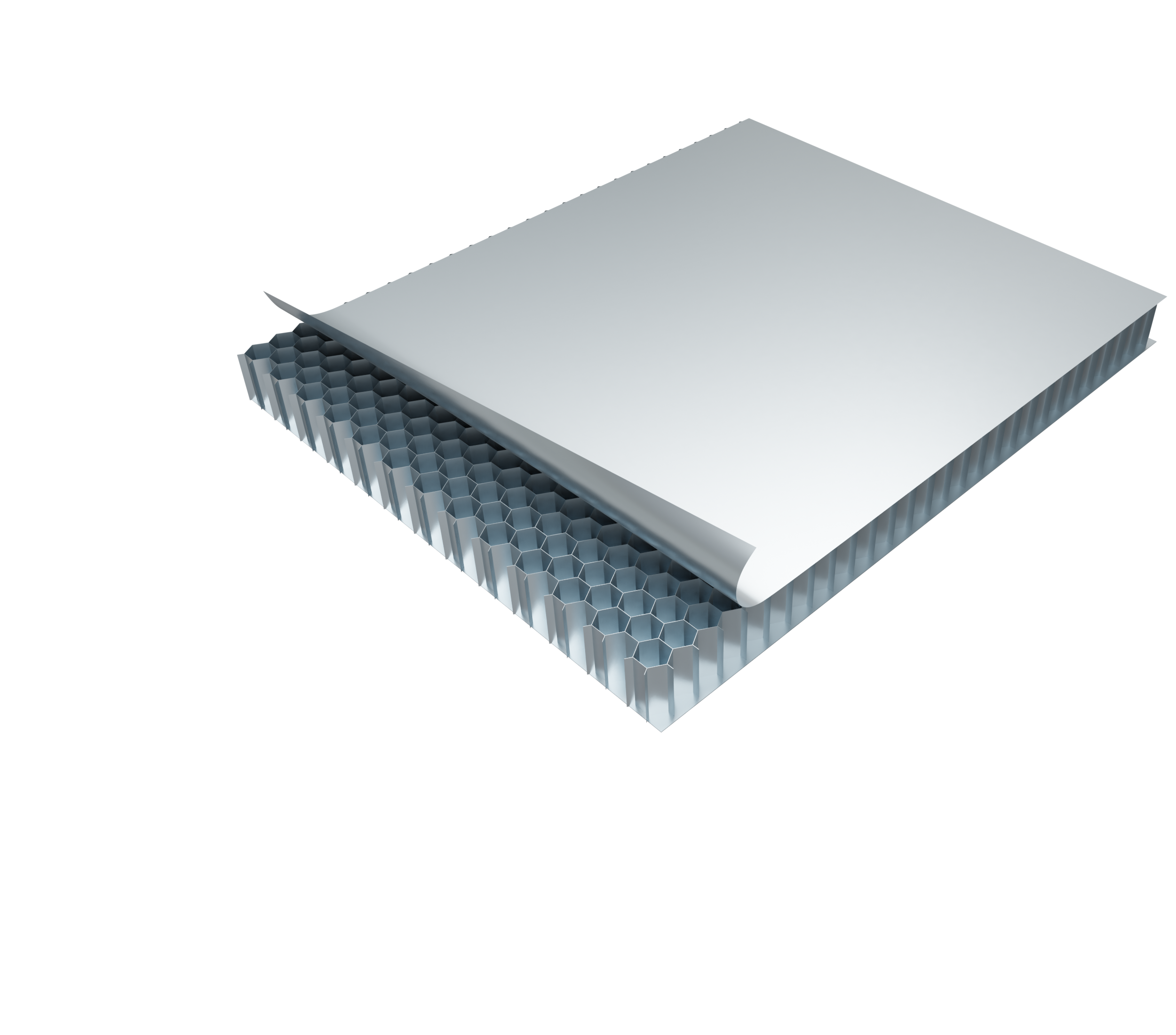
Luxboard A is a lightweight aluminium panel consisting of an aluminium honeycomb core coated with aluminium sheets on both sides.
The panel combines exeptional stability characteristics with an extreme lightweight property and is certified as non-combustible material, according to various standards and codes.
Luxboard A has a proven outstanding persistence for interior constructions in shipbuilding & railway, as well as for the truck trailer industry and general industry. It can also be found in offshore construction, design components and in machine building.
| Composition | The cover sheets and the core are bonded together with a thermoplastic adhesive which guarantees stability of the composite material up to 110°C |
| Panel thickness | minimum honeycomb thickness of 3mm + cover maximum production thickness: 50mm |
| Panel width | minimum production with: 1000 mm maximum production with: 1550 mm |
| Panel length | Continuously produced length up to 15.000 mm (due to production); Individual cuts are available from production widths |
| Core | Aluminium honeycomb core made of 3003 alloy, nominal cell diameters are: 6,4 mm ( 1/4”), 9,6 mm (3/8”) and 12,7 mm (1/2”). The densities of the core are 82 kg/m³, 50 kg/m³ bzw 38 kg/m. |
| Cover Sheets | Aluminium alloy made of 5754 H48 (standard material) guarantees high surface stability and impact strenghts. This alloy is very robust against environmental influences e.g. seawater resistancy. Standard skin thicknesses are 0.5 mm and 1.0 mm. Bespoke thicknesses are available on request. Cover sheets can be layered symmetrically on top and bottom (1mm/1mm or 0.5mm/0.5 mm) or asymmetrically (0.5 mm / 1.0 mm). Alternative alloys are available by respecting minimum order quantity. Finished/painted cover sheets are available at a mini- mum panel order quantity of 250 running meters for both sides finished. |
| Tolerances | length: + 1,0 / – 0 mm width: + 1,0 / – 0 mm thickness: + 0,1 / – 0,1 mm surface flatness: + 0,1 / – 0,1 mm dishing: < 1 mm per 1m |
| Safety | It is recommended that protective equipment such as safety glasses and breathing protection is worn during any cutting operations to avoid inhalation and eye contact with dust. Gloves should be worn to avoid cuts. Hands should be washed before eating, drinking or smoking and after finishing work. |
| Recyclabilty | Almost completely recyclable due to its consistency of more than 90 % aluminium |
| Eviromental Compatibility | Manufactured 100% chrome free |

Ceiling Panels

Wall Panels

Floor Panels

Wind Energy

Solar Panels

Caravan Interior Construction

Architecture

Truck Body Construction

Flood Protection

Milled Components

Milled Components

Profiles
Adaptations
| Edging and Bending | 1. cut the cover sheets 2. fill with two component glue 3. fold into desired position 4. fixate until glue hardens | – |
| Compounds | usage of profiles if possible | – |
| | | creation of tongue and groove joints | – |
| | | secure with adhesive and/or bolts | – |
| Edge Closing* | using profiles | * Depending on the requirement of your application |
| | | wooden inlays | | |
| | | edge sealant | | |
| | | adhesive tape | | |
| | | cover sheet folding | | |
| Fasteners Fixation | 95% of a honeycomb panel is air. Use filler resins and spacer sleeves to introduce screws and secure bolts. | – |
| | | Our experienced team will be happy to provide you with advice at any time in finding the right solution for your application. | – |
Types and Weights
| Type | Thickness* [mm] | – | – | – | Panel weight [kg/m2] | – | – |
|---|---|---|---|---|---|---|---|
| | | total | Cover Sheet | – | honeycomb comb | Cell width | – | – |
| | | | | Top | Bottom | | | 6,4 mm | 9,6 mm | 12,7 mm |
| | | | | | | | | | | 1/4″ inch | 3/8″ inch | 1/2″ inch |
| A060303 | 6 | 0,3 | 0,3 | 5,4 | 2,4 | 2,2 | 2,1 |
| A060505 | | | 0,5 | 0,5 | 5,0 | 3,4 | 3,3 | 3,2 |
| – | – | – | – | – | – | – | |
| A100303 | 10 | 0,3 | 0,3 | 9,4 | 2,7 | 2,4 | 2,3 |
| A100505 | | | 0,5 | 0,5 | 9,0 | 3,8 | 3,5 | 3,4 |
| A101010 | | | 1,0 | 1,0 | 8,0 | 6,4 | 6,1 | 6,0 |
| A101515 | | | 1,5 | 1,5 | 7,0 | 9,0 | 8,8 | 8,7 |
| – | – | – | – | – | – | – | |
| A150303 | 15 | 0,3 | 0,3 | 14,4 | 3,2 | 2,7 | 2,5 |
| A150505 | | | 0,5 | 0,5 | 14,0 | 4,2 | 3,8 | 3,6 |
| A151010 | | | 1,0 | 1,0 | 13,0 | 6,8 | 6,4 | 6,2 |
| A151515 | | | 1,5 | 1,5 | 12,0 | 9,4 | 9,1 | 8,9 |
| – | – | – | – | – | – | – | |
| A200303 | 20 | 0,3 | 0,3 | 24,4 | 4,1 | 3,3 | 3,0 |
| A200505 | | | 0,5 | 0,5 | 24,0 | 5,1 | 4,4 | 4,0 |
| A201010 | | | 1,0 | 1,0 | 23,0 | 7,7 | 7,0 | 6,7 |
| A201515 | | | 1,5 | 1,5 | 22,0 | 10,3 | 9,7 | 9,4 |
| – | – | – | – | – | – | – | |
| A250303 | 25 | 0,3 | 0,3 | 24,4 | 4,1 | 3,3 | 3,0 |
| A250505 | | | 0,5 | 0,5 | 24,0 | 5,1 | 4,4 | 4,0 |
| A251010 | | | 1,0 | 1,0 | 23,0 | 7,7 | 7,0 | 6,7 |
| A251515 | | | 1,5 | 1,5 | 22,0 | 10,3 | 9,7 | 9,4 |
| – | – | – | – | – | – | – | |
| A300303 | 30 | 0,3 | 0,3 | 29,4 | 4,5 | 3,6 | 3,2 |
| A300505 | | | 0,5 | 0,5 | 29,0 | 5,6 | 4,7 | 4,3 |
| A301010 | | | 1,0 | 1,0 | 28,0 | 8,2 | 7,3 | 6,9 |
| A301515 | | | 1,5 | 1,5 | 27,0 | 10,8 | 10,0 | 9,6 |
| Comprehensive strength | – | – | – | – | MPa** | – | – |
| | | – | – | – | – | 4,5 | 2,5 | 1,5 |
*) special thicknesses and widths on demand
**) DIN 53291, 1 MPa = 1 N/mm2
Technical Data
| Type | Thickness | – | – | Cell width | E-module of cover sheets | Tensile strength R m MPa** | Yield strength R p0,2 MPa** | Shear force during deformation* | Max. deflection under transverse force* | Theor. Flexural rigidity* | Moment of inertia* | Area moment of inertia* |
|---|---|---|---|---|---|---|---|---|---|---|---|---|
| | | total | Cover Sheet | – | | | | | | | | | | | | | | | | | | |
| | | | | top | bottom | | | | | | | | | | | | | | | | | | |
| | | mm | mm | mm | Inch – mm | N/mm2 | N | mm | kNcm²/m | cm³/m | cm⁴/m | ||
| A060505 | 6 | 0,5 | 0,5 | 3/8 – 9,6 | 70.000 | 280 | 220 | |||||
| A100505 | 10 | 0,5 | 0,5 | 3/8 – 9,6 | 70.000 | 280 | 220 | 1.294 | 2,61 | 15.820 | 4,51 | 2,26 |
| A100510 | 10 | 0,5 | 1 | 3/8 – 9,6 | 70.000 | 280 | 220 | 1.250 | 2,78 | 19.950 | 5,7 | 2,85 |
| A101010 | 10 | 1 | 1 | 3/8 – 9,6 | 70.000 | 280 | 220 | 1.400 | 7,25 | 28.350 | 8,1 | 4,05 |
| A150505 | 15 | 0,5 | 0,5 | 3/8 – 9,6 | 70.000 | 280 | 220 | 1.853 | 3,53 | 36.820 | 7,01 | 5,26 |
| A151010 | 15 | 1 | 1 | 3/8 – 9,6 | 70.000 | 280 | 220 | 1.856 | 3,28 | 68.600 | 13,07 | 9,8 |
| A200505 | 20 | 0,5 | 0,5 | 3/8 – 9,6 | 70.000 | 280 | 220 | 2.181 | 4,15 | 66.570 | 9,51 | 9,51 |
| A200510 | 20 | 0,5 | 1 | 3/8 – 9,6 | 70.000 | 280 | 220 | 2.673 | 4,31 | 86.450 | 12,35 | 12,35 |
| A201010 | 20 | 1 | 1 | 3/8 – 9,6 | 70.000 | 280 | 220 | 3.188 | 3,68 | 126.350 | 18,05 | 18,05 |
| A250505 | 25 | 0,5 | 0,5 | 3/8 – 9,6 | 70.000 | 280 | 220 | 2.550 | 5,12 | 105.070 | 12,01 | 15,01 |
| A251010 | 25 | 1 | 1 | 3/8 – 9,6 | 70.000 | 280 | 220 | 3.245 | 5,15 | 201.600 | 23,04 | 28,8 |
| A300505 | 30 | 0,5 | 0,5 | 3/8 – 9,6 | 70.000 | 280 | 220 | 2.854 | 5,69 | 152.320 | 14,5 | 21,76 |
| A300510 | 30 | 0,5 | 1 | 3/8 – 9,6 | 70.000 | 280 | 220 | 3.811 | 6,78 | 199.640 | 19,1 | 28,52 |
| A301010 | 30 | 1 | 1 | 1/4 – 6,4 | 70.000 | 280 | 220 | 6.592 | 8,80 | 294.350 | 28,03 | 42,05 |
| A200510 | 30 | 1 | 1 | 3/8 – 9,6 | 70.000 | 280 | 220 | 4.036 | 7,12 | 294.350 | 28,03 | 42,05 |
| A401010 | 40 | 1 | 1 | 1/4 – 6,4 | 70.000 | 280 | 220 | 7.900 | 11,31 | 86.450 | 38,03 | 76,05 |
| A401010 | 40 | 1 | 1 | 3/8 – 9,6 | 70.000 | 280 | 220 | 2.673 | 4,31 | 86.450 | 38,03 | 76,05 |
*) 4-point bending test in dependance on DIN 53293
**) Drum-peeling-test according to DIN 53295
Certificates
| Ship Construction | MED, IMO 0098 | Modul D Production Quality Assurance | Modul D MEDD000013Y-rev.6 |
| | | | | Module B – Type Approvals Item no. MED/3.13 non-combustible Luxboard A Wabenkern mit USCG no. 164.109 | Modul B MEDB00003ZH-rev.2 |
| | | | | Item no. MED/3.64 C-class divisions, non-combustible materials Luxboard A | Modul B MEDB00002D0-rev.1 Luxboard D |
| | | | | | | Modul B MEDB000077T Luxboard A-QA |
| | | | | | | Modul B MEDB000076N Blueboard |
| | | | | | | Modul B MEDB00002JV-rev.2 |
| | | | | Item no. MED/3.18a surface materials and floor coverings with low flame spread characteristics Luxboard A mit USCG no. 164.112 | Modul B MEDB00006H8 Luxboard D mit USCG no. 164.112 |
| | | | | | | Modul B MEDB00004HM-rev.1 Blueboard mit USCG no. 164.112 |
| | | | | | | Modul B MEDB00006H9 |
| | | U.S. Coast Guard | Aluminum honeycomb core: Item No: MED/3.13 non-flammable according to IMO FTP Code, Annex 1, part 1 USCG Approval No.: 164.109/EC0098/MEDB0003ZH-REV-1/MEDD000013Y | – |
| Architecture | DIN EN 13501-1 | A2-s1, do classification, non-combustibility | A2 – non-flammable |
| | | | | | | s1 – no smoke development |
| | | | | | | d0 – no flammable dripping/falling off |
| Rail vehicles | DIN EN 45545 | fulfills requirement set R 1 Hazard Level 3 Can be used for: | all design classes |
| in all operating classes |
Tests
Drum peeling test DIN 53 295
Testing of core connections
The drum peeling test determines the resistance of core composites to peeling forces acting perpendicular to the cover layer.
During the test, the cover layer of a core composite sample wraps around a cylindrical drum with a constant radius from the core, while the remaining part of the sandwich must be sufficiently rigid. Peeling force and distance are documented.
The average specific peeling moment is calculated from the data. For the calculation, the average tensile force [N] must be determined from the peeling diagram. The force F1 included in the calculation results from the force required to wrap the unglued cover layer sheet around the drum. To determine the force F1, the cover layer sheets were tested according to the standard.
As a result, the adhesive shows clear plastic deformation when broken, which shows that the honeycomb webs are well embedded in the adhesive and thus a strong bond. Calculation of mean specific peeling moment M:
This means:
| F m | average tensile force in N |
| M | ((Fm – F1) x (r2 – ri)/b) x [N] |
| F 1 | Force in N to align the peeling device and to wrap the glued sheet around the drum; this force must be determined through preliminary tests |
| r a | flange radius plus half the steel strip thickness in mm |
| r i | ((100+t)/2) x [mm] |
| r i | drum radius plus half the top layer thickness in mm |
| b | sample width in mm |
| Sample condition | peeling direction | F1, top layer 1mm aluminum | ra, ri, b | Average peel force F [N] | M |
| unaged | L-direction | 305 | ra = 62,65 mm | 673 | 59,6 |
| | | W-direction | | | ri = 50,5 mm | 664 | 58,2 |
| aged | L-direction | | | b = 75 mm | 682 | 61,1 |
| | | W-direction | | | 705 | 64,8 |
Bending test DIN 53 293
Testing of core connections
The test procedure is used to assess the strength and deformation properties of core bonds under 4-point loading. The testing is conducted using a bending apparatus, consisting of a bending table and a bending punch, each with two supports.
Evaluation of the 4-point bending tests according to DIN 53293
| Luxboard | – | A10 | A20 | A30 |
| Thickness (h) | [mm] | 10 | 20 | 30 |
| Traverse force (F) | [N] | 1.130 | 3.602 | 6.018 |
| Bending moment | [Nmm] | 59.324 | 189.112 | 315.919 |
| Transverse force | [N] | 565 | 1.801 | 3.009 |
| Compressive/tensile stress in surface layers | [N/mm2] | 71,53 | 98,64 | 108,68 |
| Path traverse at Fmax (fm) | [mm] | 6,74 | 4,91 | 4,31 |
| Center distance external at F max (fm) | [mm] | 6,89 | 4,94 | 4,32 |
| Bending stiffness, calculated (EI) | [Nmm2] | 1,74E + 08 | 7,51E + 08 | 1,49E + 09 |
| Shear stress | [N/mm2] | 0,63 | 0,95 | 1,04 |
Downloads
Jobs
Following positions are open. Please do not hesitate to contanct us if you have further questions.

